Attached connecting cable (0.5m length)
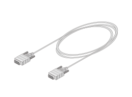
This is for the connection of two unit modules.
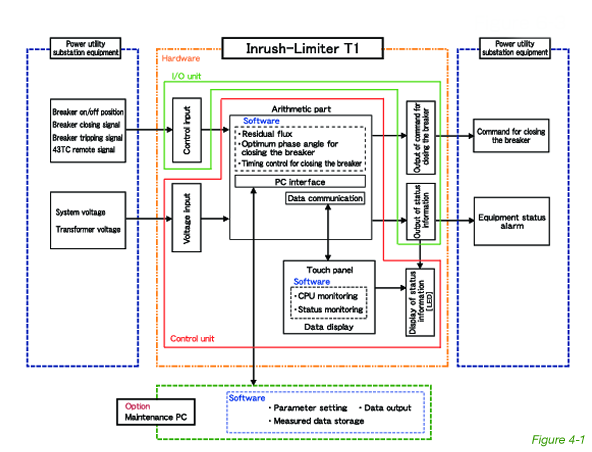
| Item | Function |
|---|---|
| Voltage Input | The secondary voltage of the VT for the system voltage (primary side of the circuit breaker for the primary side of the transformer) and transformer voltage (primary or secondary side of the transformer) is input to the control unit via an input converter. |
| Control Input | Receives an external control signal and inputs it into the control unit. |
| Output of command for closing the circuit breaker | Receives a command for closing the circuit breaker from the control unit and outputs it to the external device (circut breaker). |
| Output of status information | Outputs information about unit status and alarms to external devices. |
| Display of status information | Displays information about unit status and alarms. |
| Touch panel | Displays infpmation about operation history of a circuit breaker and alarm monitoring. |
| Arithmetic part | Performs arithmetic operation and control. It consists of a power unit. CPU unit. DI/O unit and A/D unit. |
| Maintenance PC | It provides a LAN connection to a PC intended for adjusting the interface with the controller and maintenance work. |
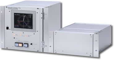
| Operation Unit | Control Unit | |
|---|---|---|
| Part no. | T1-2□□ | IL-I0-DC110V/DC125V |
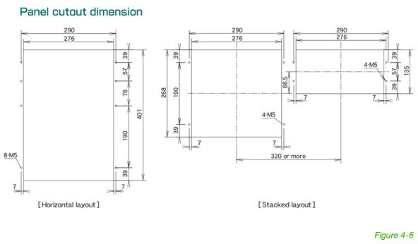
| Mounting method | Rack or panel moment | |
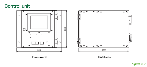
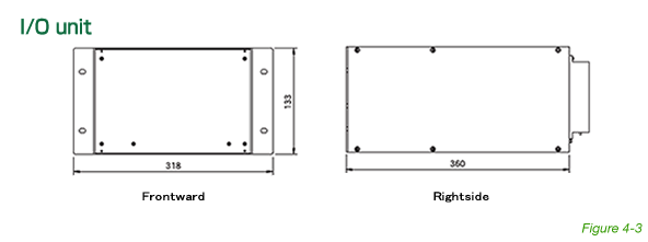
| Outer dimension W×H×D[mm] |
318 × 266 × 360 (not including projections such as terminal blocks) |
318 × 133 × 360 (not including projections such as terminal blocks) |
| Surface treatment | Silver colored anodized aluminum | |
| Weight [kg] | 9 | 7 |
| Power Supply | Power supply from the I/O unit(24VDC) | 100VDC(90-120V),200W or 125VDC(100-135V),200W (For other power supply voltage, please contact us.) |
| CPU | CPU: Atom E3845 1.91GHz Calendar backup battery life: 10 years |
- |
| Touch panel | 5.7inch(QVGA) Display colors : 65,536 Backlight service life 50,000 hours or more Touch panel service life: 1 million times or more |
- |
| Communications | Ethernet 100Base-T or above for communication with a maintenance PC. (Other communication function requests, please contact us.) |
- |
| Cooling method | Natural cooling | |
| Ambient temperature and humidity | -20℃ to 60℃(no freezing permissible)and 20% to 90%RH(no condensation permissible) | |
| Environment | Np harmful smokes or gases, salty gases, explosive gases, water drops or vapor. excessive dust or powder, excessive vibration or impact, or heat convection obstructions are permissible. |
|
| Withstand voltage* | 2000VAC, 1 minute, (Collective grounding of input terminals) *Except 24VDC circuits. |
|
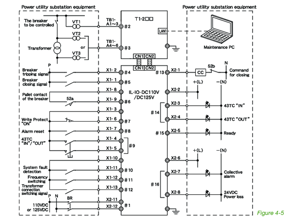
| 1 | Control power | Power | Input the control power of 110/125VDC for this unit. | 110VDC(90-120V),200W or 125VDC(100-135V),200W |
|---|---|---|---|---|
| 2 | System voltage | Analog input | Breaker primary side VT three-phase voltages to be supplied. 3-phase line voltage 110V,50/60Hz |
VT load 0.1 VA or less. |
| 3 | Transformer voltage | Breaker secondary side VT voltages (transformer HV-side or LV-side VT voltages) to be supplied. 3-phase line voltage 110V,50/60Hz |
||
| 4 | Trip signal | Digital input | Add a current relay to the final stage trip coil of the circuit breaker and connect the relay to this unit. Input the 1a signal or the circuit breaker pallet contact. |
No-voltage contacts(1a). Contact input rating: 110/125VDC,20mA or more. |
| 5 | Close signal | Signal for final stage operation of closing the circuit breaker. | ||
| 6 | The palette contacts of the associated breaker | Auxiliary contacts of the breaker to be supplied. | ||
| 7 | Write Protect “ON” | Circuit breaker primary-side auxiliary contact. | No-voltage contacts(1b). Contact input rating: 110/125VDC,20mA or more. |
|
| 8 | Alarm reset | Momentary-switch contact for resetting operation. | No-voltage contacts(1a). Contact input rating: 110/125 VDC,20mA or more. |
|
| 9 | Device enable/disable switch | Momentary-switch contact for the enabling/disabling operation.Use it when remote operation is required. | No-voltage contacts (2a, or 1a+ 1b). Contact input rating: 110/125VDC, 20mA or more. |
|
| 10 | System fault detection | To detect a system fault, a separate relay available for this purpose is required. For further details please contact us. | No-voltage contacts(1a). Contact input rating: 110/125VDC, 20mA or more. |
|
| 11 | Frequency switching(optional) | Switching the power frequency between 50 and 60 Hz. For further details please contact us. | ||
| 12 | Ttansformer connection switching(optional) | Switching between Y and △ connections for the transformer. For further details please contact us. | ||
| 13 | Command for closing | Digital output | Outputs the command for closing the circuit breaker. | Transistor output Switching capacity 110/125VDC,max. 7A |
| 14 | Device enable/disable status | Outputs the enabled/disabled state of the device, it can be used for display purpose/ Use it when the remote display is required. | Relay output Contact capacity 125VDC, max. 0.3A 110VAC, max. 2A |
|
| 15 | Ready | Contact is closed with “Ready” on. | ||
| 16 | Alarm | Contact is closed with the device fault detected. |
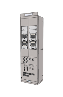
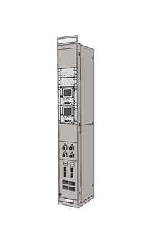
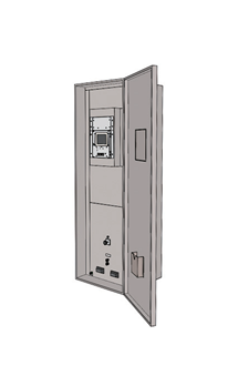
| 4 Banks (Model: IL-EC04-□) | 2 Banks (Model: IL-EC04-□) | Cabinet with the front door (Model: IL-EC01-1) | Build to order (Model: IL-ECX-□) |
|---|---|---|---|
 |
 |
 |
We offer to build to order models according to customer specifications. |
| - Frame with four mounting banks (maintenance access at front and rear)- 700 x 2300 x 450 mm (W x H x D) (Rack and panel nameplate not included.) | - Frame with two mounting banks (maintenance access at front and rear)- 350 x 2300 x 450 mm (W x H x D) (Rack and panel nameplate not included.) | - Frame with one mounting bank (maintenance access at front)- 700 x 2000 x 600 mm (W x H x D) (Rack and panel nameplate not included.) |