How Inrush Current Occurs and the Algorithm to Suppress It
When the transformer is disconnected from the system by manual operation, the three-phase cores remain magnetized, leaving residual flux φa,φb,φc in its original state.
The next time the transformer is re-energized at phase timing θcl, the initial charge of the voltage on the side of the power supply system adds an initial magnetic flux φa(tcl),φb(tcl),φc(tcl) to the cores.
If the residual flux φa,φb,φc and the initial magnetic flux φa(tcl),φb(tcl),φc(tcl) that occurs when the transformer is re-energized have the same polarity and a small scalar difference across each phase, the inrush phenomenon can be suppressed.
But if the polarity differs on any of the phases and the scalar difference is large, the transient flux in the cores will overwhelm the saturation value and generate tremendous inrush phenomenon.
Therefore, knowing what the correct scalar value is, including the polarity of the fluxes remnant in each core after the transformer is disconnected, is key to developing a control algorithm that can suppress inrush current. Incidentally, the polarity and magnitude of this residual flux φa,φb,φc is significantly different from the flux φa(top0),φb(top0),φc(top0) that remains in the cores when the transformer is disconnected at time top0.
The reason for this is illustrated below.
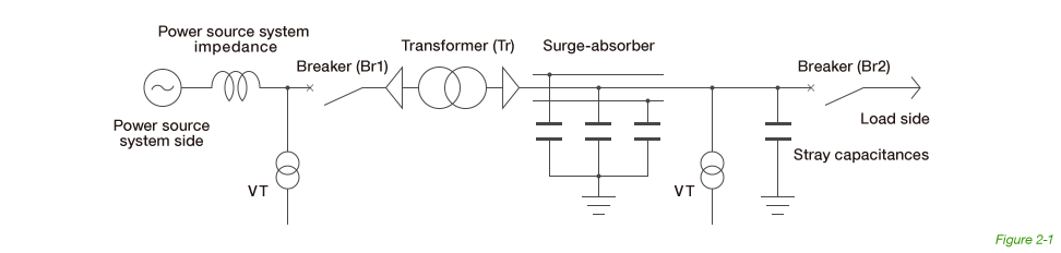
Figure 2-1 shows a representative phase of the transformer Tr circuit about to be energized from an unloaded state (where circuit breaker Br2 is disconnected).
The line from the low voltage side of the transformer coil has a loop circuit based on floating capacitors and surge absorbers.
This means that a brief transient voltage, current, and magnetic flux will occur immediately after circuit breaker Br1 on the high voltage side is disconnected.
The voltage va(t),vb(t),vc(t) and current ia(t),ib(t),ic(t) attenuate and eventually disappear as the transient phenomenon dies down top1.
The magnetic flux φa(t),φb(t),φc(t) in the cores (which is the integral of the voltage) undergoes a transient change which allows the final value at top1 to converge to a constant value φa(top1),φb(top1),φc(top1).
This convergence value is the true residual flux in the core.
Notice that the circuit is balanced on all three-phases before and after the transformer is disconnected.
If circuit breaker Br1 trips the transformer with an extremely small inrush current, all three phases will trip at the same time top0 (there is no time delay among phases as with zero-cross tripping).
As such, the conditions to keep the three-phase balanced during the transient phenomenon are preserved.
This means that the residual flux in the core is balanced across the three-phases.
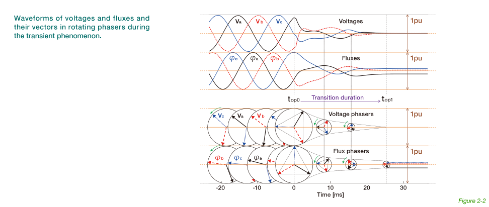
Figure 2-2 shows the transient phenomenon that was recorded by the Inrush Limiter after the transformer was disconnected.
This installation is for a power receiving transformer (220/110kVA, 250MVA, Y-Δ, 60Hz) in a substation of an electric power company.
The upper diagram shows the transient waveforms of the voltage (measured secondary VT voltage) and magnetic flux (generated by calculating the integral of the voltage).
The lower diagram is a visual representation of the voltage and magnetic flux waveforms through a rotating phaser.
The voltage phaser attenuates as it rotates and eventually disintegrates by the time top1 the transient phenomenon dies out.
The magnetic flux phaser also shrinks as it rotates, and converges into a residual flux of a certain value while remaining balanced across the three-phases at top1.
In each phase, the polarity and absolute value of the residual flux has a completely different scalar value than the magnetic flux the moment top0 the circuit breaker is disconnected.
The Inrush Limiter calculates and captures the residual fluxes in each phase in an almost balanced state.
φa(θop1),φb(θop1),φc(θop1).
When the transformer is re-energized, the phase at which the circuit breaker closes is controlled so that phase timing θcl is approximately the same as phase θop1 of the residual flux. (See our Patented Method for details on the algorithm.)
Algorithm for Suppressing Inrush Current (Patented Method)
Numerous field data from many different substations prove how effective the Inrush Limiter is at suppressing the inrush phenomenon.
See Applications for typical applications.
Although the basic theory of the Inrush Limiter’s control algorithm is field-proven, Kodensya did extensive tests with a simulated power transmission system (220 volts) to validate the control method, as reported below.
In the simulated power transmission test, the transformer was repeatedly disconnected at phase timing θop0.
Each time, the voltage waveform (actual measurements) of each phase in the transient period was recorded and used, in turn, to calculate and record the magnetic flux waveform (generated by integration), and a rotating phaser of the size and phase angle θop1 of the three-phase residual flux at the end of the transient period.
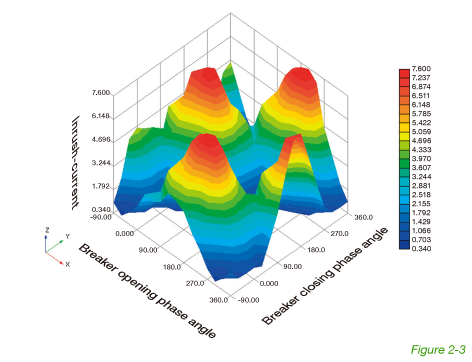
The peak inrush current (θop1,θcl,I) at phase angle θcl, at which the circuit breaker was closed to re-energize the transformer, was also recorded. Figure 2-3 shows a 3-D curved surface drawing of the results measured (θop1,θcl,I) from repeated opening and closing tests.
Figure 2-4 takes the same test results and shows the area covered by the maximum and minimum inrush current as coordinates (θop1,θcl).
This figure shows with great precision that when θop1 and θcl are in just about the same phase, inrush current I is at an extreme low, and when θop1 and θcl are at 180-degree opposite phases, inrush current I is at its peak.
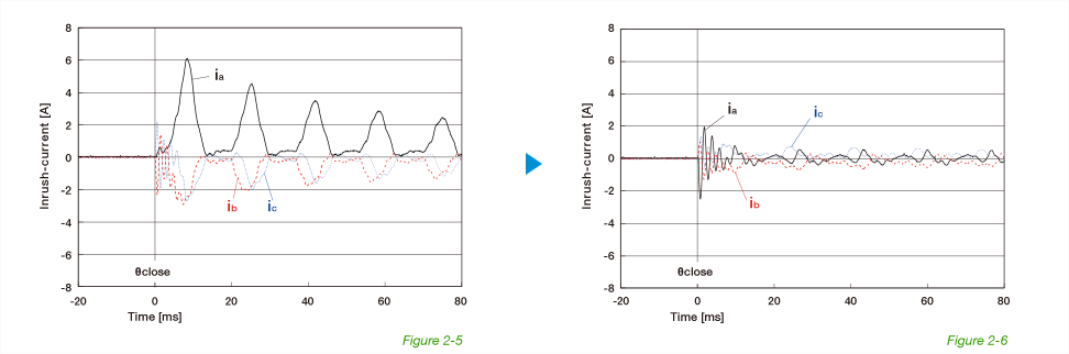
Figure 2-5 shows the peak inrush current waveform that was recorded when the circuit breaker was closed at opposite phases.
Figure 2-6 shows how virtually all inrush current is eliminated by closing the circuit breaker at the optimum phase angle (according to the algorithm of the Inrush Limiter).
Optimum Algorithm: Matching Scalar Value to the Phase with the Smallest Residual Flux
The Inrush Limiter, immediately after the transformer is disconnected, calculates and captures the true residual flux in its disintegrated state at the end of the transient phenomenon as an idle equilateral triangle at phase angle θop1.
The circuit breaker is controlled to re-energize the transformer where phase angle θcl is as close as possible to θop1.
Figure 2-7 explains this control algorithm.
The small triangle in the figure indicates the phaser for the residual flux.
The phase with the smallest scalar value (phase a in the figure) is chosen as the reference phase.
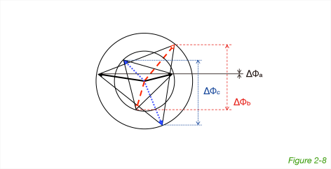
The scalar value of the reference phase a in the initial magnetic flux (the large triangle in the figure) matches the scalar value of the residual flux (becomes ∆Φa=0) at two-phase angles every cycle (Figures 2-7 and 2-8).
In figure 2-7, the polarities of the residual flux and initial magnetic flux of phase b match, and ∆Φb is sufficiently small.
This is also true for phase c. In this way, Inrush Limiter’s algorithm finds and uses the optimum phase angle at which to close the circuit breaker.
Figure 2-8 shows the other timing at which ∆Φa=0.
In this case, an extremely large inrush current would occur because the polarities of the residual flux and initial magnetic flux for phases b and c are at almost exact opposite phases, and ∆Φb, ∆Φc are extremely large.
The polarities of the fluxes for phases b and c in both Figures 2-7 and 2-8 are easy to recognize, and makes it possible to achieve the optimum phase angle that is shown in Figure 2-7.