
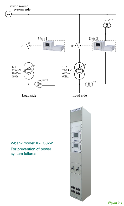
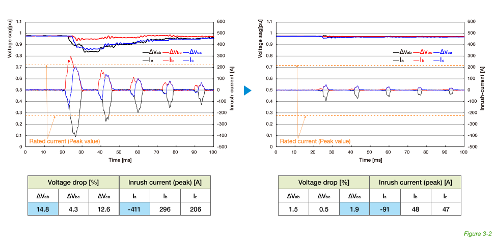
This is for an electric utility company’s substation on a remote island. The low potential of the system raised concerns about voltage drops due to the inrush current of the power receiving transformer. The Inrush Limiter T1 was installed to prevent this. Figure 3-2 shows measured waveforms, recorded during field validation testing, of the inrush current and voltage drop with and without the Inrush Limiter.
After repeated opening and closing tests without the Inrush Limiter, the inrush phenomenon showed an inrush current of 411 A and a voltage drop of 14.8%. With the Inrush Limiter, the inrush current was suppressed to 91A and the voltage drop was held to within 1.9%.
| Transformer specifications | Tr.1: 10MVA 22kV/6kV |
|---|---|
| Tr.2: 6MVA 22kV/6kV |

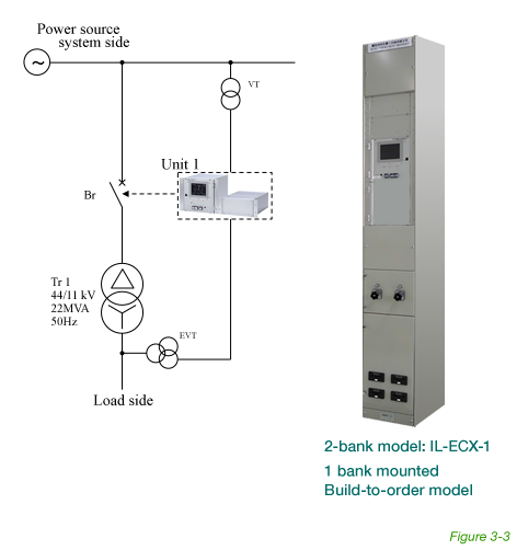
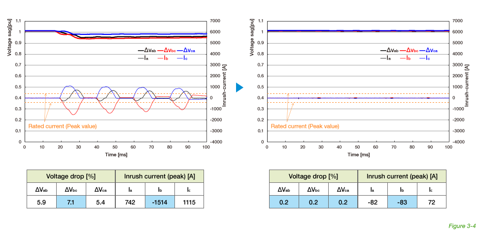
A major chemical manufacturer owns an electrical furnace and its electrical power receiving substation. The substation consists of several banks of the power receiving transformers. When they energized a transformer in one of the banks, the other banks (connected to the primary side of the power system) showed a significant voltage drop. The Inrush Limiter T1 was installed to avoid this voltage drop and the disturbances it causes on manufacturing activities. Figure 3-4 shows measured waveforms, recorded during field validation testing, of the inrush current and voltage drop with and without the Inrush Limiter.
After repeated opening and closing tests without the Inrush Limiter, the inrush phenomenon showed an inrush current of 1,514A and a voltage drop of 7.1%. With the Inrush Limiter, the inrush current was suppressed to 83A and the voltage drop was held to within 0.2%.
This manufacturer used a circuit breaker with a resistor for many years to suppress inrush currents in their 66-kV electrical power receiving substation. (The 66-kV serial resistor is used with an auxiliary circuit breaker to limit inrush current when the breaker is closed.) The Inrush Limiter has rendered these resistors obsolete, which are now removed.
| Transformer specifications | 22MVA 44kV/11kV |
|---|
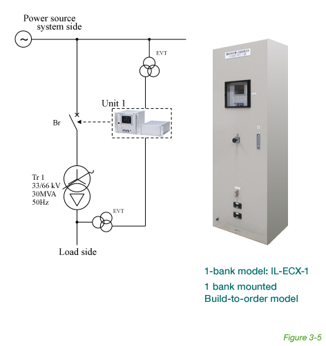
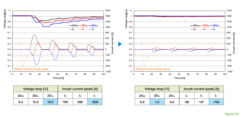
Studies at an interconnected substation for a wind power generating system revealed voltage drops of 20% when the transformer was connected. It was necessary to suppress this to within 5%. The Inrush Limiter achieved less than 3%.
(Each of the following countermeasures to achieve 5% or less were rendered obsolete:
After repeated opening and closing tests without the Inrush Limiter, the inrush phenomenon showed an inrush current of 839A and a voltage drop of 19.5%. With the Inrush Limiter, the inrush current was suppressed to 164A and the voltage drop was held to within 1.5%.
- Installation of a diesel generator
- Specially designed transformer (change in leakage impedance, etc.)
- Use of a serially-connected resistor and circuit breaker
| Transformer specifications | 30MVA 33kV/66kV |
|---|
Installed Base
| Field Application | Units |
|---|---|
| Factory (Extra high-voltage substation) | 68 |
| Wind Power Station | 19 |
| Photovoltaic Power Station | 25 |
| Biomass Power Station | 13 |
| Smart Grid Community | 3 |
| Hydro Power Station | 11 |
| Power Company’s Substation | 23 |
| Public Facility | 5 |
| Research Institute | 3 |
| Railway Company’s Substation | 27 |
| Ship | 2 |
| Overseas | 9 |